# How Wind Loads Are Applied To The Structure

Shapemaker automatically calculates wind forces in accordance with EN 1993-1-4:2005 and EN 1993-3-1:2006, based on the structural model and user-defined ancillaries. Wind loads are computed separately for the main structure, whether it's a lattice tower, monopole, or guyed mast, and for the ancillaries, which can be discrete or linear elements.‍

## **Case study**

* 3-legged lattice tower made of 6 panels.
* Panel type (from bottom to top): K, M, K, M, K, M.
* Wind direction: 0°.‍

### **Wind forces on structure**

Wind forces are initially generated at the midpoint of each panel and then distributed to all nodes on the legs associated with that panel in the structural model.

<figure><img src="https://cdn.prod.website-files.com/62066ef6f9af0e41c7315af2/686516ce38ddc6bd75c407d9_tower-sketch-automatically.png" alt=""><figcaption><p>
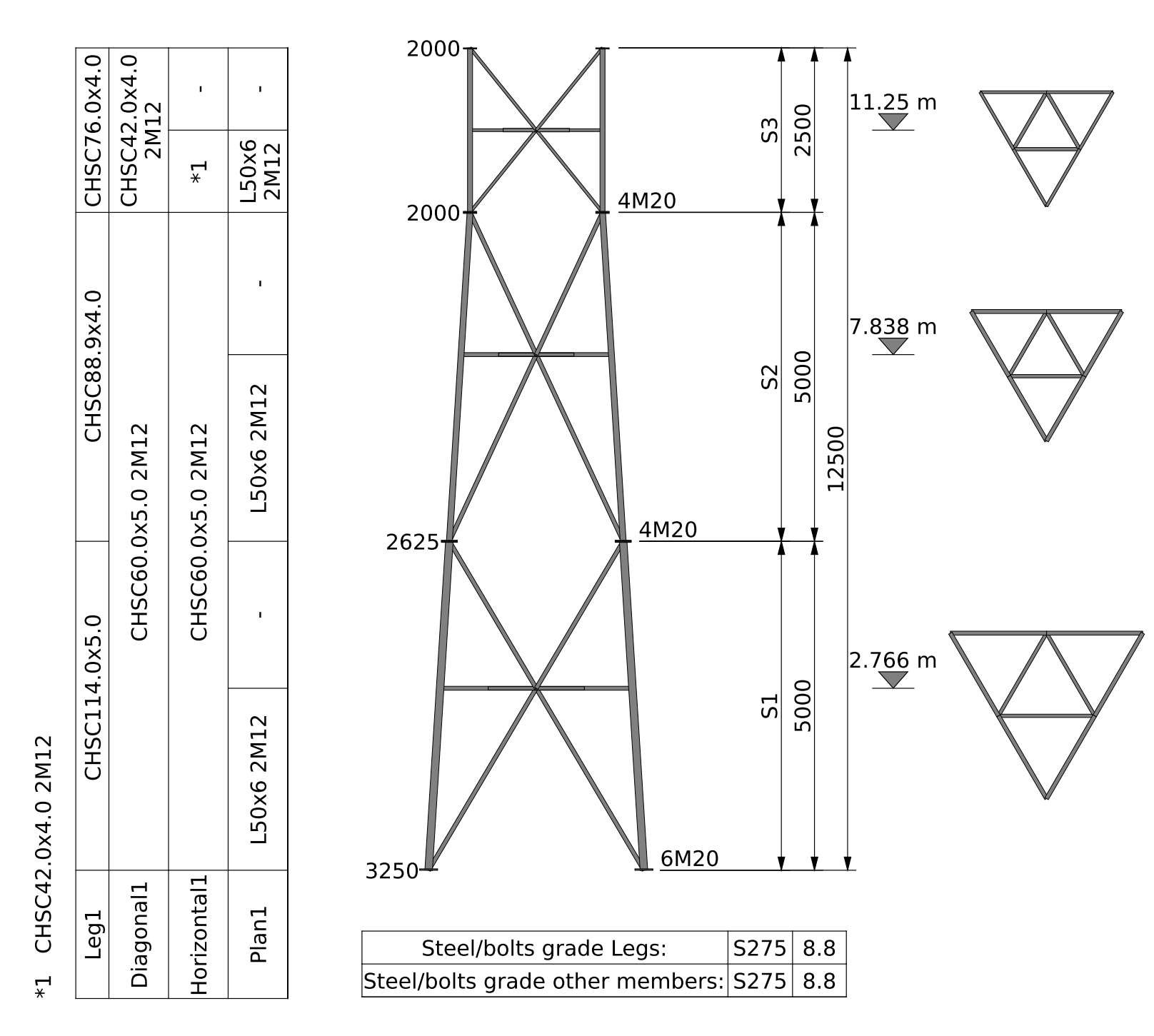
Lattice tower drawings automatically generated in Shapemaker</p></figcaption></figure>

Wind forces on the bare structure extracted from the Shapemaker report are presented below. The "z" column represents the midpoint of each "M" and "K" panel. The wind forces at each "z" elevation along with all the required parameters are calculated automatically.

<figure><img src="https://cdn.prod.website-files.com/62066ef6f9af0e41c7315af2/686517031c1b506346b0bf35_table1-structure.png" alt=""><figcaption></figcaption></figure>

Then, the wind forces from the last column (F<sub>T,W</sub>(z)) are applied in all the nodes of the lattice model.

<figure><img src="https://cdn.prod.website-files.com/62066ef6f9af0e41c7315af2/68651719382c777a8f8987aa_FEA-wireframe-structure-general.png" alt=""><figcaption><p>
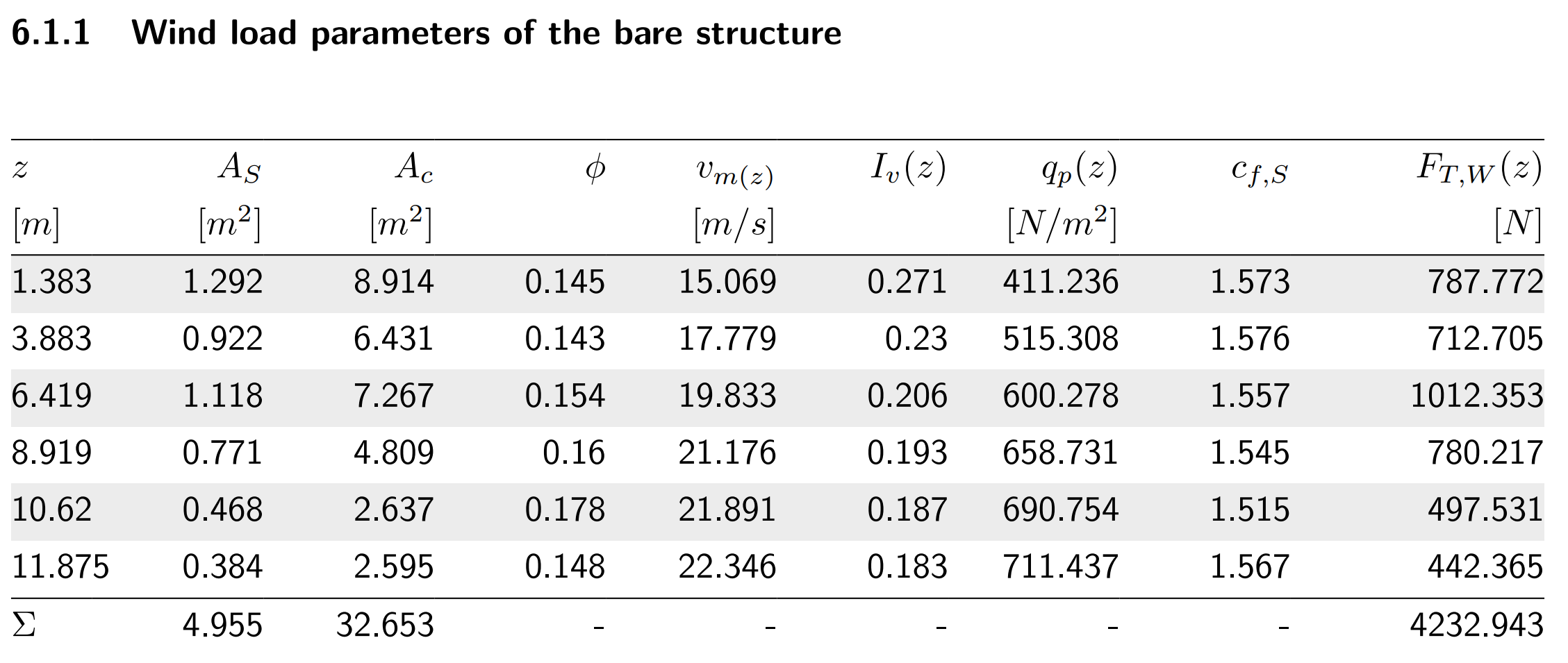
FEA wireframe structural model in Shapemaker</p></figcaption></figure>

The 787.772 N force at z=1.383m is divided by 6 (nodes) and applied in each node of the panel. The next one, at z=3.883m, is also divided by 6 (nodes) and summed up with the forces coming from the below and above panels. The sketch below explains this process.

<figure><img src="https://cdn.prod.website-files.com/62066ef6f9af0e41c7315af2/68651744385a78353a58ebbd_FEA-wireframe-structure-closeup.png" alt=""><figcaption></figcaption></figure>

All the forces can be checked separately for the structure and ancillaries in our FEA viewer after you run an analysis and get the results. The results are presented per each combination depending on the wind direction.

‍

### **Wind forces on discrete ancillaries**

Wind forces are generated based on user input for each type of discrete ancillaries. See here how [Shapemaker calculates EPA for discrete ancillaries](https://www.shapemaker.io/blog/calculating-ancillary-epa-in-shapemaker-using-eurocode-and-tia-222).

<figure><img src="https://cdn.prod.website-files.com/62066ef6f9af0e41c7315af2/686517ae3c6b629bd08d8b07_tower-with-ancillaries-sketch-automatically.png" alt=""><figcaption><p>
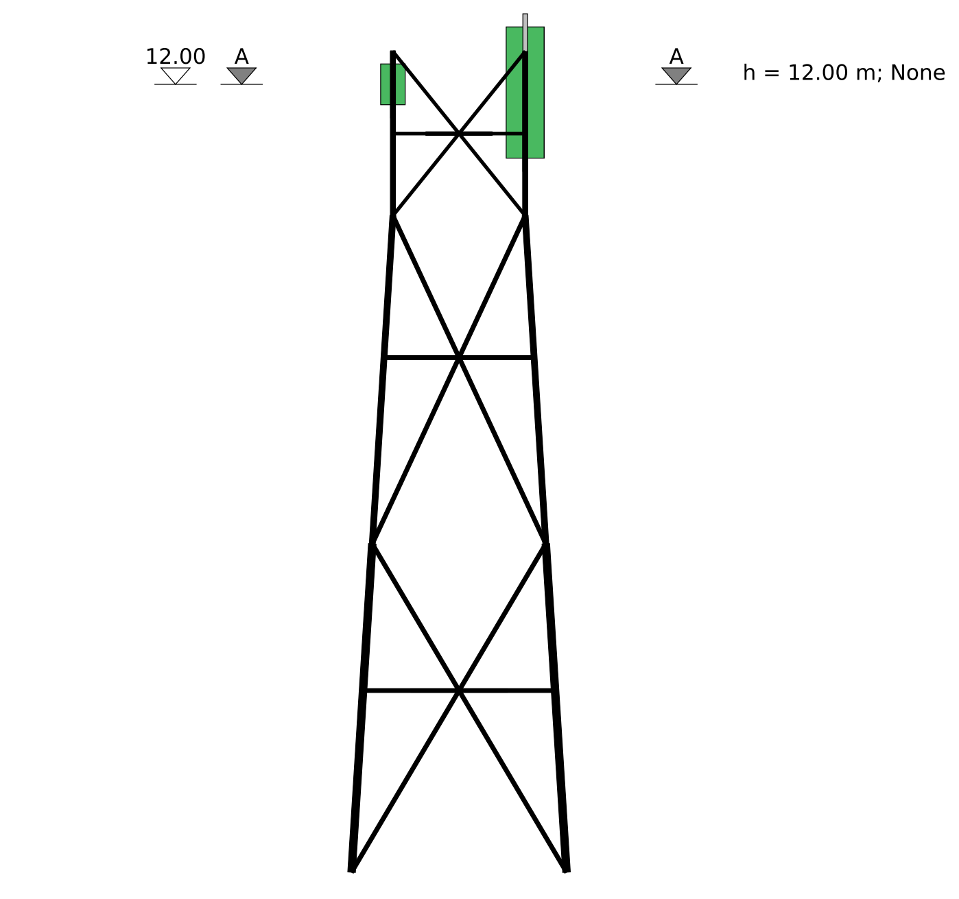
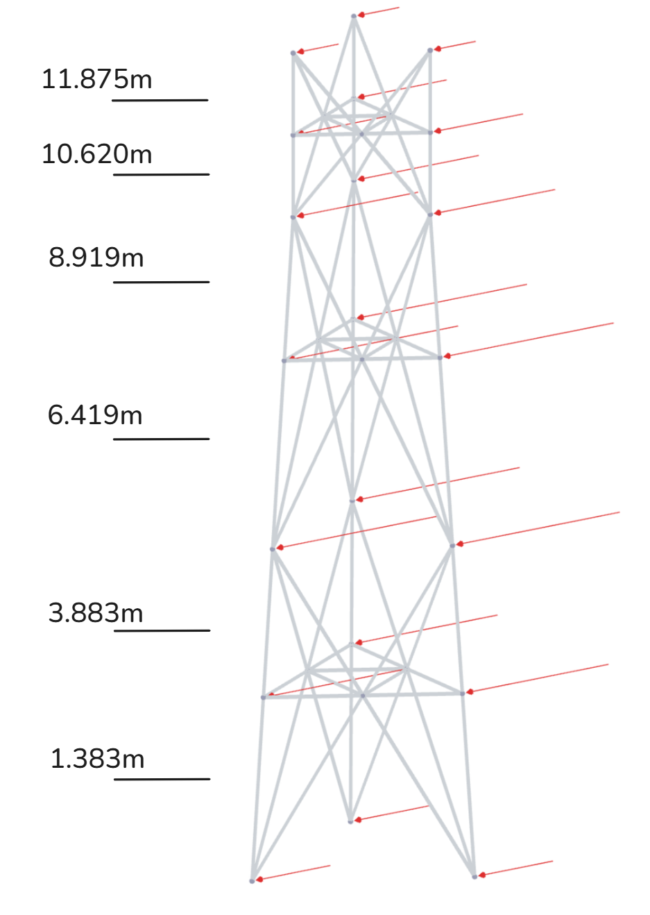
Tower with ancillaries automatically generated in Shapemaker</p></figcaption></figure>

<figure><img src="https://cdn.prod.website-files.com/62066ef6f9af0e41c7315af2/686517bd382c777a8f89d2ab_tower-with-ancillaries-3d-view.png" alt=""><figcaption><p>
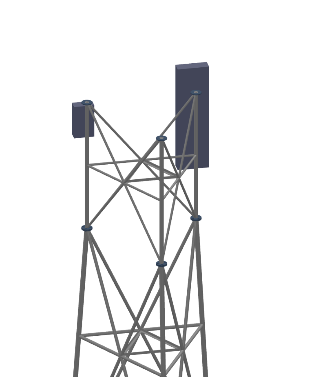
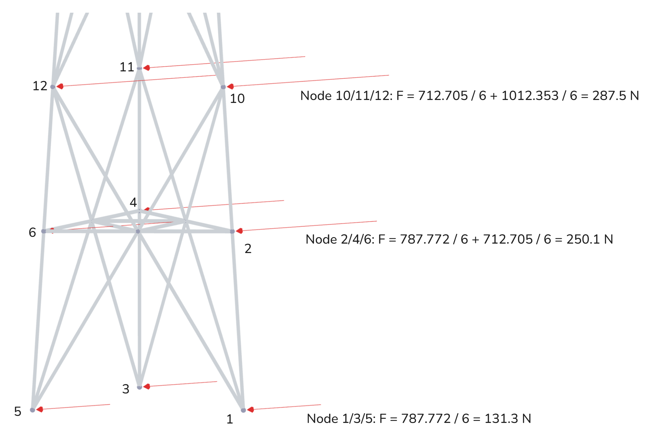
3D view with the ancillaries in Shapemaker</p></figcaption></figure>

Wind forces on discrete ancillaries extracted from the Shapemaker report are presented below.

<figure><img src="https://cdn.prod.website-files.com/62066ef6f9af0e41c7315af2/686517cdbd2048e3e736bd6c_table2-discrete.png" alt=""><figcaption></figcaption></figure>

All forces from the discrete ancillaries in Shapemaker are distributed to the nodes of the nearest FEA leg member as a pair of two forces.

For example, the 1255.2 N force from the Kathrein 800 10403 antenna is distributed between nodes 22 and 28, while the 254.1 N force from the Ericsson AIR 3278 antenna is distributed between nodes 23 and 29. Depending on the antenna's position along the FEA member, some nodes may receive a larger or smaller portion of the total force. In the case of the Ericsson AIR 3278, which is located at 12.0 m, closer to node 29 (12.5 m) than node 23 (11.25 m), node 29 will receive a proportionally greater share of the force.

<figure><img src="https://cdn.prod.website-files.com/62066ef6f9af0e41c7315af2/686517e3385a78353a592fff_FEA-wireframe-discrete-closeup.png" alt=""><figcaption></figcaption></figure>

### **Wind forces on linear ancillaries**

Wind forces from feeders and ladders are generated based on user-input of front and side projected areas and their lengths. The linear ancillaries are automatically positioned in the center of the tower and the forces are distributed evenly to all legs.

Wind forces on linear ancillaries are extracted from the Shapemaker report.

<figure><img src="https://cdn.prod.website-files.com/62066ef6f9af0e41c7315af2/686517f90d20437537832c0f_table3-linear.png" alt=""><figcaption></figcaption></figure>

Then, all the forces from the last column are distributed in the same manner as for the structure. The force is divided by 6 (nodes) and summed up with the forces coming from the below and above panels. See the sketch below explaining the process.

<figure><img src="https://cdn.prod.website-files.com/62066ef6f9af0e41c7315af2/686518076184195f17eefbea_FEA-wireframe-linear-closeup.png" alt=""><figcaption></figcaption></figure>

<br>


---

# Agent Instructions: Querying This Documentation

If you need additional information that is not directly available in this page, you can query the documentation dynamically by asking a question.

Perform an HTTP GET request on the current page URL with the `ask` query parameter:

```
GET https://docs.shapemaker.io/technical-details/how-wind-loads-are-applied-to-the-structure.md?ask=<question>
```

The question should be specific, self-contained, and written in natural language.
The response will contain a direct answer to the question and relevant excerpts and sources from the documentation.

Use this mechanism when the answer is not explicitly present in the current page, you need clarification or additional context, or you want to retrieve related documentation sections.
